Overview
[ Top
| MIO-D
| Return to Vertical Spools
]
MIO-D2
(#1056)
Technical Details
I acquired my MIO-D2 from CWC Supply in 2007.
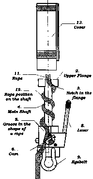
The top central portion of the MIO-D2 is a forged aluminum
shank with a rope guide and attachment hole at each end. The central
shaft is 20.3 mm. in diameter and 109 mm. long. The
top of the shaft is capped by a 21 mm. thick, 54 mm.
diameter disk with two 11 mm. rope grooves spaced 180°
apart. Each of the grooves has a distinct hook, and a rounded
rope channel on the underside that guides the rope to start a
left-hand helix around the shaft. The bottom of the shaft ends
in an 87 mm. tall quasi-cylindrical section. The upper 53 mm.
are 54.6 mm. in diameter, the remainder 59.2 mm. The
bottom 28 mm. has a chordal sector removed, and two slots
cut to accept a 9.6 mm. clevis (held by a 9.6 mm. pin)
that serves as the attachment point. There is another rounded
area removed at the base. A 10 mm. rope groove cuts through
the upper 53 mm. portion, sloping down and left until it intersects
the chordal cutout.
The rear of the upper cylinder has a 28 mm. round-end
milled slot. This slot accepts a 9.6 mm. shaft that serves
as an axle and a 38 mm. long, 25.3 mm./31.8 mm.
diameter stepped bushing that serves as a mount for the brake
lever. There is a washer between the bushing and main body of
the device.A 9.6 mm. diameter, 132 mm. long lever screws
into a bushing mounted on the shaft. The lever bends forward 90°
and then upward at a second, 80° bend. The end of the lever
has an 18 mm. tall, 12.7 mm./20.3 mm. diameter
tip shaped like the frustum of a cone with one side removed. A
moderately strong spring forces the lever outward, where a bend
in the stainless steel plate stops its travel.
The front end of the lever axle shaft passes through a stainless
steel plate screwed to the front of the cylindrical section (at
another cutout), where it is welded to a D-shaped cam. The lever
spring holds the cam against the rope. Squeezing the lever toward
the central column rotates the cam away from the rope.
Finally, there is an 8.5 mm. spring-loaded cover retaining
pin on the side opposite the lever.
The cover is made from 3.0 mm. sheet aluminum rolled into a
near-cylinder, with a 12.7 mm. gap for inserting the rope.
The cover is 183 mm. long and its internal diameter is 54.1 mm.
There are parallel (not diamond) knurled bands near the top and
bottom of the cover. A subrectangular cutout near the bottom (adjacent
to the rope entry groove) allows the cover to clear the lever
assembly. A beveled 9.1 mm. hole aligns with the cover retaining
pin.
One side of the clevis is forged with "USA," "1T,"
"CHICAGO," "3/8," and "E." The top
of the device is stamped with the serial number "1294."
The cover has two stickers. The smaller sticker says "Pat.
No. 6,814,185" (with quotes). The larger reads as follows:
 MIO® ROPE DESCENT DEVICE
DANGER
DO NOT ATTEMPT TO USE THIS
ROPE DESCENDER WITHOUT TRAINING
FROM A QUALIFIED INSTRUCTOR.
INJURY OR DEATH MAY OCCUR.
WARNING
USE ONLY APPROVED ROPE
TYPE AND SIZE (see MANUAL)
DO NOT USE THIS DEVICE WITHOUT
THE COVER IN ITS PROPER
LOCKED POSITION.
THE SPEED OF DESCENT DEPENDS
ON THE NUMBER OF THE WRAPS
AROUND THE SHAFT, TYPE OF ROPE,
AND WORKING HEIGHT.
MIO MECHANICAL CORPORATION
PHILADELPHIA 215/671-0226
msemio@earthlink.net
 This
is a MIO-D2 reminds me of the Sky Genie with its central column and slotted cover, and of the Frost
Rope-riders which have the same column and cover arrangement,
but add a brake mechanism (the mechanism used on the Frost
Rope-riders and MIO-D2 are completely different). Most cavers
and climbers might think that the MIO-D2 is an odd design, and
I would agree with those who think that it is too heavy, but the
MIO-D2 was designed for industrial use. I acquired mine from a
window cleaning supplier, and it appears that window cleaners
are a major part of the target market for the MIO-D2. Working
all day with both hands while hanging on rope is not the same
as rappelling another virgin pit while exploring an new cave,
or rapping off a first ascent. These differences justify the device.
The MIO-D2 came with a rather nice 14 page manual. The manual
targets window washers, and shows some typical roof top rigging
setups. There are some nice drawings that look like patent illustrations,
followed by detailed illustrated instructions on how to use the
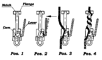
device. Rigging is straightforward: take the cover off, open the
cam by depressing the lever, wind the rope around the shaft in
the proper direction (there is a red [meaning stop!] mark painted
inside the device to mark the wrong direction), and replace the
cover.
The manual includes a table recommending three rope types,
none of which match normal caving or climbing rope. It includes
tables recommending a specific number of wraps depending on the
worker’s weigh (including equipment; the manual explains how to
add the worker’s weight and the equipment weight to get a total
weight). In all cases, the recommended number of wraps does not
change for drops ranging from 65 to 300 feet (~20 to 90 m.)
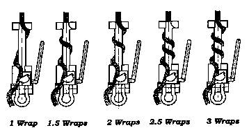
The manual even includes a figure showing how to count the number
of wraps, and I sincerely hope that my readers do not need that
much help.

[ Top
| MIO-D2
| MIO-D
| Return to Vertical Spools
]
MIO-D
(#1067)
Technical Details
I acquired my MIO-D from CWC Supply in 2007.
The MIO-D adds a centrifugal overspeed device to the basic
design of the MIO-D2, so I shaded the common part of the following
description in gray:
The top central portion of the MIO-D is a forged aluminum shank with a rope guide
and attachment hole at each end. The central shaft is 20.4 mm. in diameter and 108 mm.
long. The top of the shaft is capped by a 21 mm. thick, 54 mm.
diameter disk with two 11 mm. rope grooves spaced 180°
apart. Each of the grooves has a distinct hook, and a rounded
rope channel on the underside that guides the rope to start a
left-hand helix around the shaft. The bottom of the shaft ends
in a 53 mm. tall, 54.6 mm. in diameter cylindrical
section. A 10 mm. rope groove cuts
through the upper 53 mm. portion, sloping down and left.
The rear of the upper cylinder has a
28 mm. round-end milled slot. This slot accepts a 9.6 mm.
shaft that serves as an axle and a 38 mm. long, 25.3 mm./31.8 mm.
diameter stepped bushing that serves as a mount for the brake
lever. There is a washer between the bushing and main body of
the device. A 9.6 mm. diameter, 138 mm.
long lever screws into a bushing mounted on the shaft. The lever
bends forward 90° and then upward at a second, 80° bend.
The end of the lever has an 18 mm. tall, 12.7 mm./20.3 mm.
diameter tip shaped like the frustum of a cone with one side removed.
A moderately strong spring forces the lever outward, where a bend
in the stainless steel plate stops its travel.
The front end of the lever axle shaft
passes through a stainless steel plate screwed to the front of
the cylindrical section (at another cutout), where it is welded
to a D-shaped cam. The lever spring holds the cam against the
rope. Squeezing the lever toward the central column rotates the
cam away from the rope.
Finally, there is an 8.5 mm. spring-loaded
cover retaining pin on the side opposite the lever.
Below the upper cylinder and lever assembly is slightly larger
cylindrical section with one side removed, which intersects a
74 mm. diameter, 44 mm. long horizontal cylinder that
holds the overspeed device. The overspeed device has a cast aluminum
V-groove sheave with six internal ribs. Three screws attach the
sheave to an internal centrifugal clutch. Details of the clutch
are not visible without disassembling the device. The inner surface
of the V-groove intersects one of the screw holes, obviously not
by intent. The opposite side of the overspeed housing is sealed
with a 3.4 mm. thick aluminum plate held in place by three
screws.
There is a hook attached to the side of the overspeed housing,
underneath the control lever. The hook is made from 7.9 mm.
stainless steel rod. It pivots in a cylindrical hole made by bending
a piece of 19 mm. by 3.2 mm. stainless steel into a
loop. The pivot end of the hook is reduced in diameter, and a
nut and two washers hold it in position. The distal end extends
outward, bends 90° downward, then curves back up to form a
30 mm. wide, 48 mm. high hook. The rope leaving the
overspeed sheave should pass through this hook.
A 45 mm. wide, 21 mm. thick tab extends below the
overspeed housing to form the eye for clipping in.
The cover is made from 3.0 mm. sheet
aluminum rolled into a near-cylinder, with a 12.7 mm. gap
for inserting the rope. The cover is 183 mm. long and its
internal diameter is 54.1 mm. There are parallel (not diamond)
knurled bands near the top and bottom of the cover. A subrectangular
cutout near the bottom (adjacent to the rope entry groove) allows
the cover to clear the lever assembly. A beveled 9.1 mm.
hole aligns with the cover retaining pin.
The top of the device is stamped with
the serial number "1158."  The cover has two stickers. The smaller sticker
says "Pat. No. 6,814,185" (with quotes). The left
side of the larger sticker reads as follows:
MIO®ROPE DESCENT DEVICE
DANGER
DO NOT ATTEMPT TO USE THIS
ROPE DESCENDER WITHOUT TRAINING
FROM A QUALIFIED INSTRUCTOR.
INJURY OR DEATH MAY OCCUR.
WARNING
USE ONLY APPROVED ROPE
TYPE AND SIZE (see MANUAL)
DO NOT USE THIS DEVICE WITHOUT
THE COVER IN ITS PROPER
LOCKED POSITION.
THE SPEED OF DESCENT DEPENDS
ON THE NUMBER OF THE WRAPS
AROUND THE SHAFT, TYPE OF ROPE,
AND WORKING HEIGHT.
MIO MECHANICAL CORPORATION
PHILADELPHIA 215/671-0226
msemio@earthlink.net
The right side of the larger sticker has "MODEL MIO®-D"
above two illustrations of the descender opened for rigging. The
left illustration has 3 turns rigged and the right has 2.5. The
text under the figures is as follows:
| |
FOR EXAMPLE RECOMMENDED |
3 TURNS
180-220 lbs
|
21/2 TURNS
150-180 lbs
|
|
SEE MANUAL FOR MORE DETAILS |
Many of my comments on the MIO-D2 apply to the MIO-D as well,
so I will concentrate on the overspeed device here. Naturally,
the overspeed device makes the MIO-D much larger than the MIO-D2.
Is it worth it? For my caving and climbing, of course not, but
for window washers, it may very well justify itself. Spending
entire days just hanging around can lead to inattention, as can
having both hands occupied.
Does it work? According to the manual (this time, 20 pages,
with more nice drawings), the overspeed device will lock at about
7 to 7.5 ft/s (just over 2 m.s) within about 0.4 s, giving a stopping
distance of about 3 feet (1 meter). The maximum dynamic load imposed
with recommended ropes would be on the order of 750 to 800 lbf
(3.5 kN). I don't have the laboratory equipment to verify these
numbers, but my own tests are consistent with these results.
[ Top
| MIO-D2
| MIO-D
]


 This
is a MIO-D2 reminds me of the
