Technical Details
I made my Storrick – Kosorukov Triangle (Косоруков Треугольник) in 2021.
My Triangle is 150 mm. tall, 91 mm. wide, 40 mm. thick, and weighs 201 g.
 The plans for this descender were published in a fascinating 1986 Russian book (Само-дельное Туристское Снаряжениеб Москва Физкультура и Спорт 1986) containing plans for all sorts of outdoor gear. The book credits Yuri Kosorukov (Юрий Косоруков) with the design. Rather than describe the device, I'll provide my translation of the description from page 220 of that book:
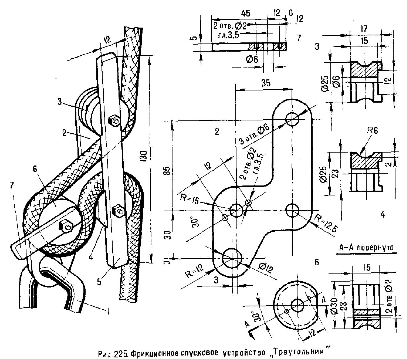
Frictional descent device "Triangle" (fig. 225)
Does not twist the rope and weighs about 180 g. When fastened with a carabiner (1) to the harness, it is always ready for use.
The device consists of a body (2), the contour of which can be simplified to a triangle with preservation of center-to-center dimensions and loaded sections, two rollers (3) and (4) with grooves for the bar (5). The rollers (4) and (6) have holes for threading the rope. The steel pins, driven into the holes with a diameter of 2 mm. of the roller (6), prevent it and the small bar (7) from rotating. The device is assembled on three steel M6 screws and nuts. The rest of the parts are made of alloy D16. (Author Y. Kosorukov, Moscow.)
Naturally, when given a book with plans for making home-made SRT equipment, I could not resist the temptation to go to the shop and get to work.
Machining and assembling the Triangle was straightforward. I tried to follow the published plans closely, but I made several lazy-man concessions to my living in a primitive country that has been insanely failing to adopt the metric system despite attempts dating back to Jefferson in 1793.
- I made the two bars from 1/2”x3/16” (12.7x4.8 mm.) bar stock instead of the specified 12x5 mm.
- The two hidden anti-rotation pins are 1/8” (3.2 mm) instead of 2 mm. (5/64”). You can't see them, 1/8” is a common round stock size here, and I like the larger pins anyhow. I used a #30 drill (0.1285”) for the pin holes to provide some clearance for assembly.
- The main plate started as ¼” (6.35 mm) thick, but I milled it to 5 mm, mainly to give a nicer finish. The plans did not specify its thickness and 5 mm. is a reasonable guess. Note that the plan for this plate is not drawn to scale.
- Although not specified, I threaded the bollards. You cannot see this, but it helps hold things together better than just relying on the nuts.
- I originally drilled a 12 mm. eye as the plans called for, but later reamed it to ½” (12.7 mm) to get a better finish. It is still too small for many carabiners.
- I used ASTM 6061-T6 and 6061-T6511 instead of the D16T specified in the book. The latter is similar to 2024-T4.
I did not round the ends of the bars because the plans did not call for doing so, but it would look better if I had.
The tight bends around the two lower bollards means that this is not an ideal device for very stiff ropes. For limp ropes, it gives less friction than I would like.

For far more content, use a larger monitor and a full-width window.
Hundreds of cell phone users complained and asked me to for a simpler, mobile friendly site. In particular, they wanted me to limit each page to a small number of pictures and minimize my use of text. This new site provides what they asked for.


