Technical Details
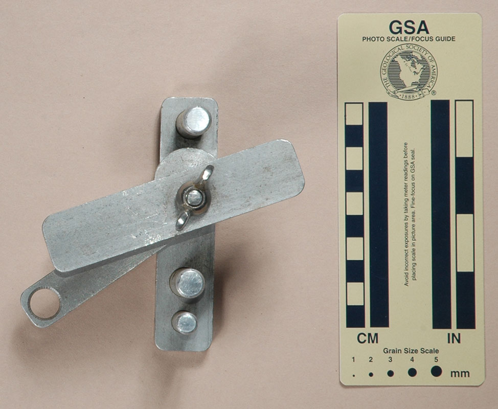
Bill Varnedoe gave me this descender in August 2000. He didn't
know the history behind it; however, we believe it dates from
the 1960’s.
The frame is made from two 3/8" by 1" by 4-1/2"
(9.8 mm. by 25.4 mm. by 112.8 mm.) pieces of aluminum,
probably 6061-T6. These are connected by two 1/2" (12.7 mm.)
and one 3/8" (9.8 mm.) aluminum rods that fit into holes
frilled part-way through the side pieces. The rods are pinned
to one of the frame pieces. When assembled, the side pieces are
32.5 mm. apart (inside dimension). The cam is a piece of
1-1/4" (31.8 mm.) aluminum rod drilled off-center, and
mounted on a 5/16" (8 mm.) stainless steel bolt. The
head of the bolt was cut off, and pressed into one of the frame
pieces where it was pinned in place. A second pin passes through
the bolt to hold the cam in place. A wing nut secures the assembly,
and the bolt threads have been mangled so that the wing nut will
not come off. A lever made from 1/4" by 3/4" (6.4 mm.
by 19.2 mm.) aluminum fits in a slot milled into the cam.
A 1/2" (12.7 mm.) hole is drilled in the end of the lever.
Rappelling with this device is interesting. There is no room
to clip in with a carabiner, so a sling must be available. There
is considerable friction when it is used on 11 mm. rope,
which is close to the limit on what will fit. The lever must be
pushed upward to descend. If the lever is released, rope friction
turns the cam in the direction that will stop the descent.

For far more content, use a larger monitor and a full-width window.
Hundreds of cell phone users complained and asked me to for a simpler, mobile friendly site. In particular, they wanted me to limit each page to a small number of pictures and minimize my use of text. This new site provides what they asked for.