Overview
[ Top
| Version B
| Version C
| Version D
| Return to Misc. Descenders
]
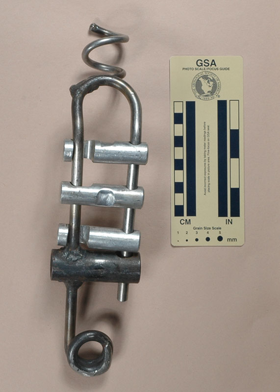
Version A
(#462)
Technical Details
I made this J-Bar around 1978.
This J-Bar is 300 mm. tall, 79 mm. wide, 75 mm. thick, and weighs 620 g.
The frame is hot-bent 321 stainless steel that my father originally had made for me as a rack frame. I removed the threaded portion and bent the top 45°. I made the top coil from stainless steel rod and the bottom bar from some mild steel pipe, and then brazed them to the frame.
Despite a superficial resemblance, J-bars are not racks and they function in a very different way. The bottom bar is welded in place, so it does not move. The standing line passes through the rope guide, under the
fixed bar, and zigzags upward through the moving bars, then down.
Not only does this give friction by normal snubbing, but increasing
the tension on the tag end squeezes the moving bars together and
against the fixed bar. Using the J-bar feels like having power
brakes on rope, and indeed, for drops of over 100 meters or so,
the tag end must be lifted to descend, making one feel that they
are pulling themselves down the pit. On shorter drops, it performs
well.
I should have bent it 100° for operational flexibility. A 100° bend creates a shelf at the top that allows running the tag end over the top to reduce friction on long drops.
The brake bars on this J-bar have L-shaped grooves rather than 45° slots because the machinist who made these did not follow the drawing. The L-slots make the bars difficult to open. This J-bar was an opportunity to get these bars off my racks and use them for something else.
The J-bar has gone out of fashion, but it once was a popular
caving device. Curiously, I've never seen an article describing the original design. I've found several articles describing modifications and showing modified J-bars, but nothing about the originals. Apparently they were so well known that nobody thought that their design or use needed any comment.
[ Top
| Version A
| Version C
| Version D
| Return to Misc. Descenders
]
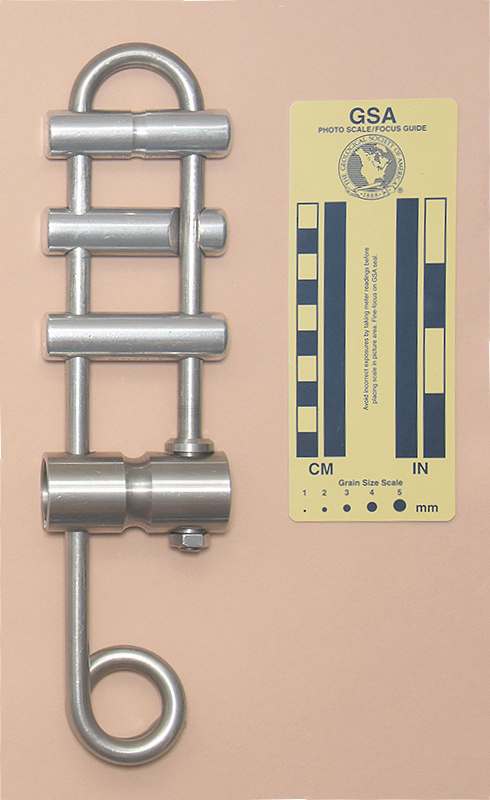
Version B
(#3091)
Technical Details
I made this J-Bar in 2021.
This J-Bar is 279 mm. tall, 69 mm. wide, 30 mm. thick, and weighs 693 g.
The frame is a stainless steel Speleoshoppe short rack frame that I bought as new old stock from Speleoshoppe in 2021. The aluminum bars are Speleoshoppe Rockfarer bars, acquired from Speleoshoppe at the same time. I turned a shallow guide groove in the top bar.
The lower bar and its support bushing are turned from 304 stainless steel.
I turned a 2.5-mm. deep guide groove in the lower bar. I bored the axis of the lower bar to reduce weight, leaving a 3.2 mm. wall at each end and a 6.3 mm. wall in the center (3.8 mm. beneath the groove).
On the closed side of the frame, I drilled the lower bar to match the frame diameter as closely as possible (start undersize and work up with letter drills), then milled slots to the top inside and bottom outside so that the bar could slip over the top of the frame. This approach provided the tight tolerance needed to ensure that the outside of the top slot and inside of the bottom slot contact the frame when the bar is square to the frame, preventing it from tilting upwards on the closed side of the frame.
The support bushing is threaded onto the end of the frame. It holds the lower bar down. Most of the central hole in the bushing is drilled for a clearance fit with the frame, but the lower portion is drilled smaller and threaded to match the 3/8-UNC thread turned on the end of the frame. The bushing fits through slots in the lower bar. These slots allow the frame to flex so the user can open the aluminum bars for rigging the rope.
I wanted to make a stainless steel J-Bar without any welding. Welding 304 and 316 stainless steels can lead to recrystallization in the heat-affected zone, and this design eliminates that potential cause of catastrophic failure.
[ Top
| Version A
| Version B
| Version D
| Return to Misc. Descenders
]
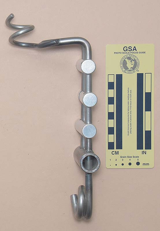
Version C
(#3208)
Technical Details
I made the parts for this J-Bar in late 2021 and Amy Skowronski welded it for me in 2022.
This J-bar is 282 mm. tall, 73 mm. wide, 107 mm. thick, and weighs 687 g.
The frame and rope guide are made from 1018 cold rolled steel. The fixed bar is made from 1-inch iron pipe.
The three aluminum bars are Speleoshoppe Rockfarer bars stamped with "ROCKFARER."
The top bend is 100°, allowing the rappeller to run the rope over the frame top to reduce friction on long drops. If this isn't done, the rope weight applies the power brakes and the user needs to pull themselves down the drop.
I based this J-bar on Version D, but omitted the spacers.
[ Top
| Version A
| Version B
| Version D
| Return to Misc. Descenders
]
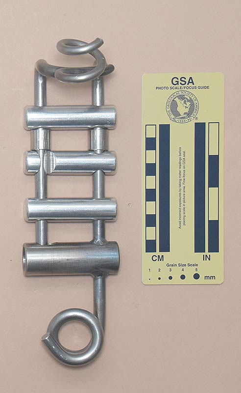
Version D
(#3209)
Technical Details
 I made the parts for this J-Bar in late 2021 and Amy Skowronski welded it for me in 2022.
This J-bar is 282 mm. tall, 73 mm. wide, 107 mm. thick, and weighs 687 g.
The frame and rope guide are made from 1018 cold rolled steel. The fixed bar is made from 1-inch iron pipe. The spacers are made from 304 stainless steel.
The three aluminum bars are Speleoshoppe Rockfarer bars stamped with "ROCKFARER."
I patterned this J-bar after the drawing in an old article by John Patten (Patten, John, 1967. "J-bar Modified." The Huntsville Grotto News, v. 8, #5, pp. 105-106. Reprinted using black ink in the 1967 Speleo Digest, pp. 3-22 to 3-24). Traditional J-bars had too much friction for some people, leading them to having to pull themselves down a drop. John added spacers to reduce friction. His drawing in put the spacers above the fixed bar, while I put them between the top two bars. Why did I place these differently? Because of course I did. If desired, one of the spacers can be slid to the lower position, although this cants the bars to some degree.
.
[ Top
| Version A
| Version B
| Version C
| Version D
]