Overview
[ Top
| Version B
| Version C
| Return to Brake Bar Descenders
]
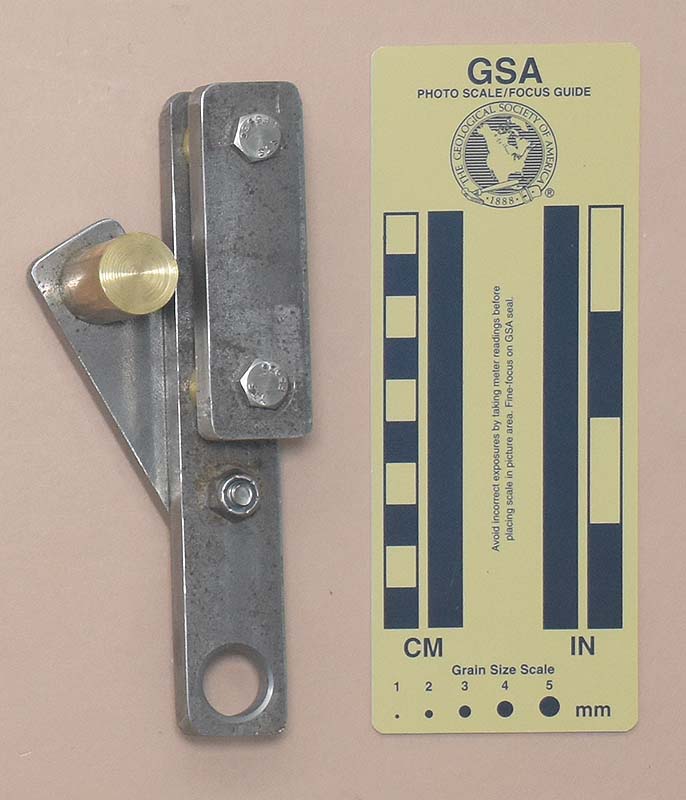
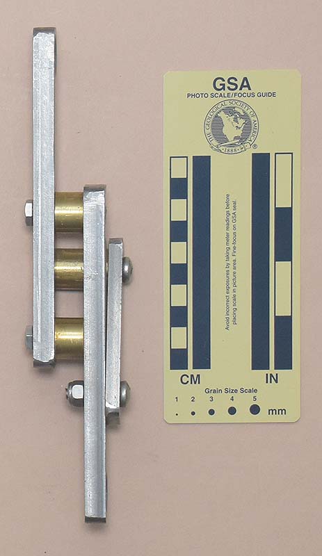
Version A
(#3216)
Technical Details
I built this device in 2022.
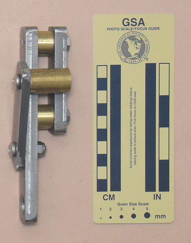
My Storrick – Geffner, Version A is 152 mm. tall, 47 mm. wide, 51 mm. thick, and weighs 662 g.
The frame is made from two pieces of 1" by 3/8" (25 by 9.5 mm.) 1018 steel. The front plate is 3-1.4" (83 mm.) long; the rear 6" (152 mm.) These are connected by two 1/2" (12.7 mm.) long, 3/4" (19.2 mm.) diameter brass brake bars, held in place by 1/4" (6.4 mm.) stainless steel bolts threaded into tapped holes in the long strap. I arranged the bolts so that the friction of the rope would act to tighten the bars against the long strap, but also drilled 1/8" (3.4 mm.) holes through the rear strap and bars, and inserted roll pins to prevent rotation. A 5/8" (16 mm.) hole drilled in the long strap plate provides a clip-in point.
The middle brake bar pivots on a lever made from 1" by 4
" (25 by 6.4 mm.) 1018 steel. A third brake bar, 3/4" (19.2 mm.) in both diameter
and 1-1/4" (32 mm.) length is, mounted on the end of the lever arm. This brake bar
is threaded, and rope friction acts to tighten this bar as well.
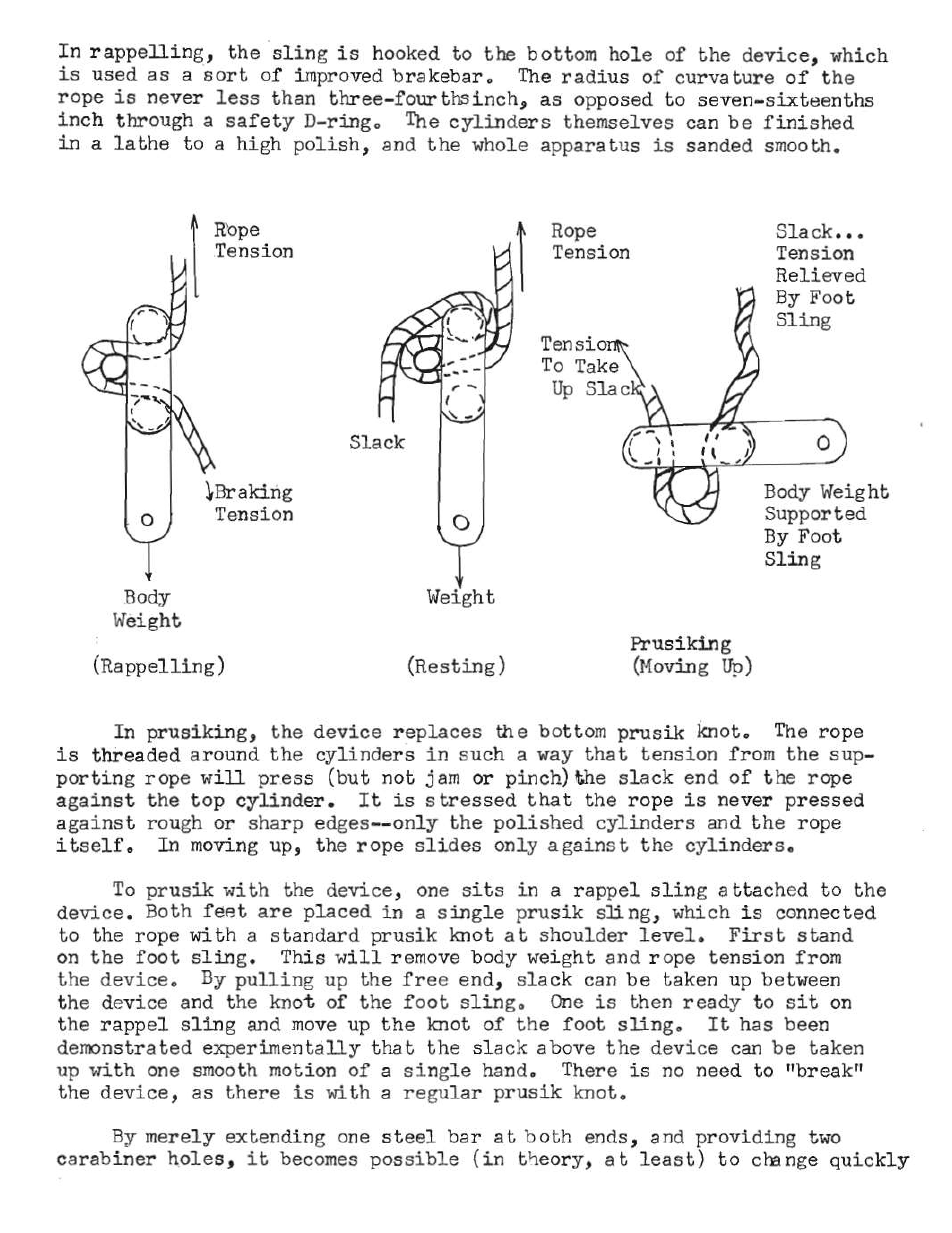
Sam Geffner described a "combination rappel and prusik device" in 1961 (The Tech Explorer, 5(2), 13-15; reprinted in the 1961 Speleo Digest). Sam described two versions - a single-ended one and a double-ended one. He did not provide engineering drawings. This descender is based on his descriptions. I followed Sam’s dimensions where given, and scaled the remaining dimensions from his sketches. The result is slightly heavier than Sam reported, likely the result of a heavier swing arm or a longer central bar.
The Geffner is an old design dating from the days of body rappels
and prusik knot ascents. It is a simple device, easy to manufacture
at home, but lacking in modern sophistication. In practice, it
acts much like any other brake bar rig. The rope has a greater
contact angle than it does with a single carabiner
with brake bar, so it provides more friction. The designer
can vary the friction by spacing the two fixed brake bars closer
(more friction) or farther apart (less friction); however, getting
them too close together (so that the rope is pinched between the
moving and fixed bars) will cause the device to lock rather than
run smoothly.
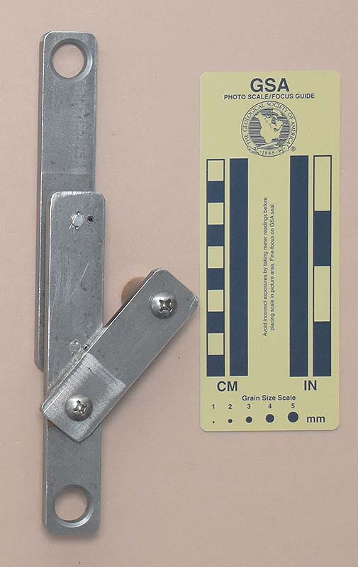
Mounting the lever on a separate pivot requires making the
device longer; however, by doing so, one could choose dimensions
that would allow the arm to move to either side of the device.
This could pose a hazard, since the brake bars would try to unscrew
on one side. If you try this, please pin the bars. An advantage
is that one could align the lever with the frame for easier packing.
[ Top
| Version A
| Version C
| Return to Brake Bar Descenders
]
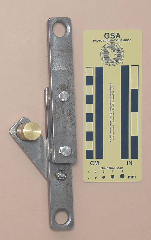
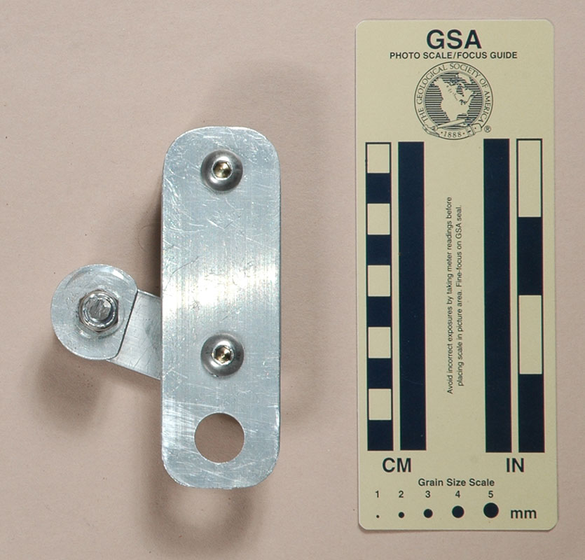
Version B
(#3217)
Technical Details
I built this device in 2022.
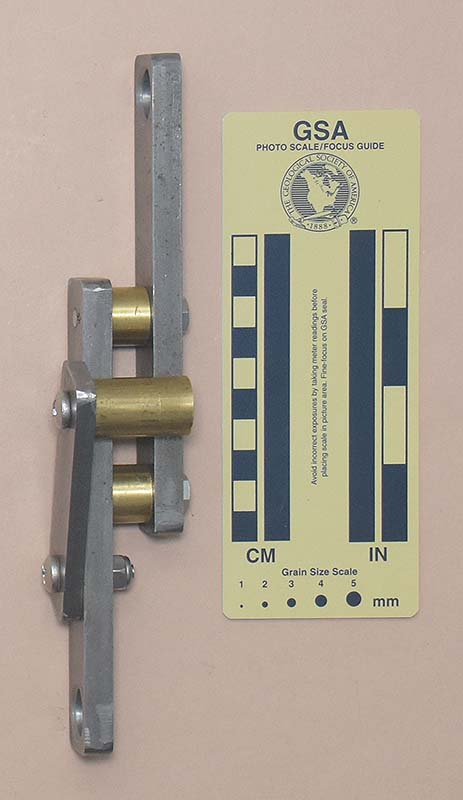
My Storrick – Geffner, Version B is 224 mm. tall, 47 mm. wide, 52 mm. thick, and weighs 778 g.
Version B replaces the short front strap of Version A with a long one with the same dimensions as the rear strap.
Sam describes using his device as an ascender, and suggested this modification to make changeovers easier. At the time of his writing, he had not made the modifications and I don't know if he ever did.
In 1961, the
idea was marginally worth trying. I cannot imagine why anyone would want
to do that in this day in age, except as an academic exercise.
[ Top
| Version A
| Version B
| Return to Brake Bar Descenders
]
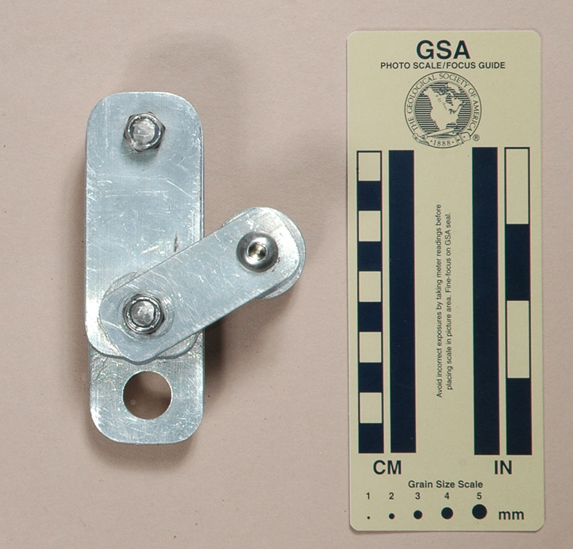
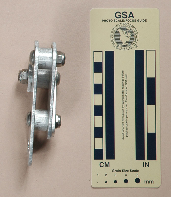
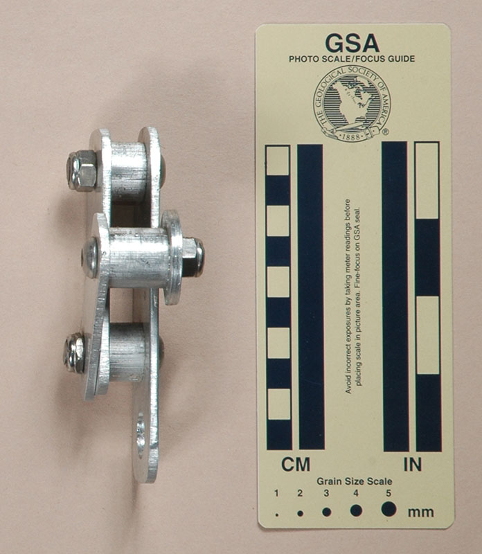
Version C
(#937)
Technical Details
I built this device in 2004.
The frame is made from two pieces of 1-1/2" by 1/8"
(32 by 3.8 mm.) 6061-T6 aluminum. [Sam recommended using 3/8"
(9.5 mm.) steel, but did not specify if this was the width,
thickness or both]. The front plate is 81 mm. long; the rear
115 mm. These are connected by two 1/2" (12.7 mm.)
long, 3/4" (19.2 mm.) diameter 6061-T6 aluminum brake
bars, held in place by 5/16" (8.2 mm.) stainless steel
hex-head cap screws with nylon-insert lock nuts. I threaded both
brake bars, and arranged the bolts so that the friction of the
rope would act to tighten the bars on the cap screws. A 5/8"
(16 mm.) hole drilled in the back plate provides a clip-in
point.
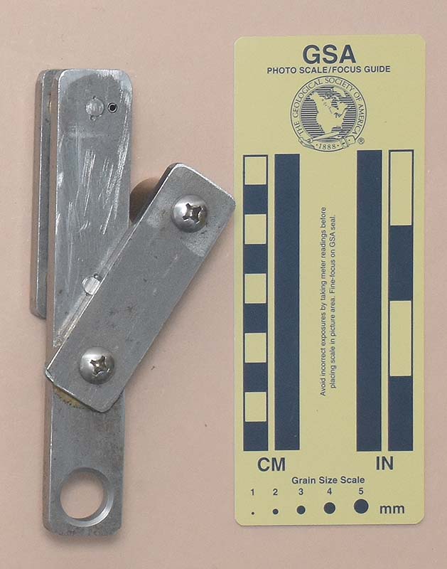
The middle brake bar pivots on a lever made from 1" by
1/8" (25 by 3.8 mm.) 6061-T6 aluminum. My lever pivots
on a cylindrical area turned into the lower stainless steel nut.
There is a third brake bar, 3/4" (19.2 mm.) in both diameter
and length, mounted on the end of the lever arm. This brake bar
is threaded as well. Note that the hex-head cap screw passes in
the opposite direction as the others - this is to ensure that
rope friction acts to tighten this bar as well. I added an aluminum
washer (cut with a hole saw) at the end of the brake bar to provide
a positive engagement to help the brake bar resist lateral motion. A flat cut in the washer provides
rope clearance for rigging.
This descender is based on Sam Geffner's
descriptions; however, I made a few modifications of my own. Using aluminum resulted in a much lighter device, and mounting the lever arm on the lower bar bolt resulted in a more compact device.
In modern times, one should not take this device too seriously.
[ Top
| Version A
| Version B
| Version C
]