Overview
[ Top
| Todd-Storrick
| Return to Lever Box Belay
]
Todd
(#1616)
Technical Details
I acquired my Todd Handled Belay Device from Peter Todd in
2008.
This Todd Handled Belay Device is 208 mm. tall, 51 mm. wide,
72 mm. thick, and weighs 922 g. It consists of a body, cover plate,
and cam assembly. The body is milled from a 51 mm. x by 140 mm.
x 25.4 mm. block of 6061-T6 aluminum. It has a 12.7 mm.
hole 15.9 mm. from the top and right side for that allows
mounting the cover plate on a home-made 1/2-13 UNC stainless steel
bolt. The bolt is secured with a stainless steel lock nut. The
rope channel is a 63.5 mm. high, 15.9 mm. deep slot whose
top edge is 31.8 mm. below the top of the block. A 12.7 mm.
hole for the cam axle is drilled 25.7 mm. below the top of
the slot and 22.2 mm. from the left side of the block. The
bottom of the block is milled to a semicircle, and a 21 mm.
hole is drilled for the attachment carabiner. The cover is made
from a 9.5 mm. piece of 6061-T6 cut to the same outline as
the body, except that a curved slot extends from the axle hole
to the right side of the cover plate.
The cam is a 34.9 mm. diameter, 15.9 mm. thick piece
of 6061-T6 with a flat milled in one side and a 12.7 mm.
hole drilled 6.4 mm. off center. The cam is attached to the
axle with a set screw. The axle is stainless steel, 12.7 mm.
in diameter with a 10.1 mm. diameter head. The axle extends
25.4 mm. beyond the back side of the body. Two aluminum blocks
bolted together clamp the back side of the axle pin. One block
is 21.7 mm. high, the other 33.1 mm., and both are 44.5 mm.
wide by 25.4 mm. thick. A 12.7 mm. stainless steel rod
is threaded into the larger block and extends 118 mm. from
the block to form a handle.
There are no markings on the device.
Peter Todd sent me pictures of his belayer in October 2008,
along with the following description:
I created this device as an
art project two years ago. We had an assignment to take an "everyday"
mechanical device and recreate it, with a twist. So, I took a
grigri, and recreated it, the twist being the 1 kg. weight
and total lack of any agency approvals. :) It’s beefy to say
the least, all constructed out of 6061 bars and stainless steel.
Most ’biners won't fit it, I designed it around an especially
large one that I bought specifically for the project. The main
axle is half an inch, although one defect in the design is my
planned press-fit of the cam to the axle wasn't secure enough,
so I ended up pinning it instead. I've tested it with a 100 ft.
rappel in the stairwell of my old apartment building, which proved
the action to be very smooth and controllable, so much so you
could control the rappel without actually gripping on the brake
hand.
No plans for full-scale production, although if you know a bunch
of "bigger-is-better" buyers I could be convinced to make
a version for 1" rope.
I sent the following reply:
Oh, WOW!!!, Peter, this is
really cool!! I love it!! I don't suppose that I could talk you
into making one for me, but perhaps you could send me either
drawings, or a good set of pictures from various viewpoints with
a machinist’s scale in them so that I could make my own?
Much to my surprise, Peter sent the following reply:
Well, actually, I’d be very
happy to trade what blueprints I have, and the authentic Todd
Handled Belay Device by internationally famous artist Peter Todd
(I wish!) for an authentic Storrick Handled Belay Device, by internationally
famous collector and vertical device expert Gary Storrick (at
least that one’s true) when you get the chance to build one. Your
mill looks bigger than the tiny Sherline I did the bulk of the
work on it with. Just be nice in your review, my main design
goal was to make something that worked as quickly as possible
with some big chunks of metal I had lying around. :)
I would like to emphasize that Peter’s original was an art project, and
not a serious attempt to design a better version of the Grigri.
Peter’s device is quite heavy, but it works reasonably well. My
greatest concern with it is that if the cam spins on the axle,
the belayer will lose the ability to lower the climber.
It is very important that the belayer rig the device correctly
so that the handle is on the same side of the device as the rope
enters; otherwise, the device will not lock if the belayed climber
falls. The resulting post-impact gooey mess could ruin a climbing
partnership.
[ Top
| Todd
| Return to Lever Box Belay
]
Todd-Storrick
(#1617)
Technical Details
I made my Todd-Storrick Handled Belay Device in late 2008.
This version is based on Peter’s design, with few changes,
so I'll use the same description in gray and indicate changes
in black:
The Todd -Storrick Handled Belay Device
is 210 mm. tall, 47 mm. wide, 67 mm. thick, and weighs
756 g.It
consists of a body, cover plate, and cam assembly. The body is
milled from a 47 mm. x by 140 mm.
x 25.4 mm. block of 6061-T6 aluminum. It has a 12.7 mm.
hole 15.9 mm. from the top and right side for that allows
mounting the cover plate on a commercial
1/2-13 UNC stainless steel bolt. The bolt is secured with a stainless
steel lock nut. The rope channel is a 63.5 mm. high, 15.9 mm.
deep slot whose top edge is 31.8 mm. below the top of the
block. A 12.7 mm. hole for the cam axle is drilled 25.7 mm
below the top of the slot and 22.2 mm. from the left side
of the block. The bottom of the block is milled to a semicircle,
and a 21 mm. hole is drilled for the attachment carabiner.
The cover is made from a 9.5 mm. piece of 6061-T6 cut to
the same outline as the body, except that a curved slot extends
from the axle hole to the right side of the cover plate.
The cam is a 34.9 mm. diameter, 15.9 mm
thick piece of 6061-T6 [deleted text] with a 12.7 mm. square hole broached 6.4 mm. off center. The axle is stainless
steel with five sections. Starting
at the front, there is a 19.1 mm. diameter, 5 mm. thick
head. Next is a 12.7 mm. diameter, 9.5 mm. long cylindrical
section for the cover plate slot, followed by a 12.7 mm.
square section that press fits into the cam. Next is another 12.7 mm.
diameter, 9.5 mm. long cylindrical section where the axle
passes through the body. Finally, there is a 9.5 mm. square
section that extends 25.4 mm.
beyond the back side of the body. A machined handle block
made from a 44.7 mm. long piece of 25.4 mm. 6061-T6
square bar stock clamps over the axle. A
10.1 mm. stainless steel rod
is threaded into the [deleted text] block and extends 128 mm.
from the block to form a handle. A
hidden stainless steel pin in the threaded end of the handle fits
into a matching hole in the axle, thereby keeping the handle from
coming off if the clamping screws loosen.
There are no markings on the device.
As the emails quoted above show, I made this version to trade
to Peter, and in the process, I made one for myself. The major
change that I made was to use a more complex axle to reduce the chances
of the cam or handle turning. If either were to spin, the results
would be unpleasant. Mine is also slightly smaller than Peter’s,
mostly because of the material that I had handy.
 |
 |
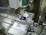 |
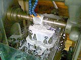
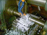
Squaring the Body
|
Roughing the Body Slot
|
Finishing the Body Slot
|
 |
 |
 |
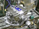
Slotting the Cover
|
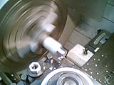
Turning the Handle Block
|
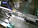
Milling the Axle Squares
|
[ Top
| Todd
| Todd-Storrick
]


