Overview
[ Top
| v. B
| v. C
| v. D
| v. E
| v. F
| v. G
| LWO
| "S" v. A
| "S" v. B
| Return to L.C. Ascenders
]
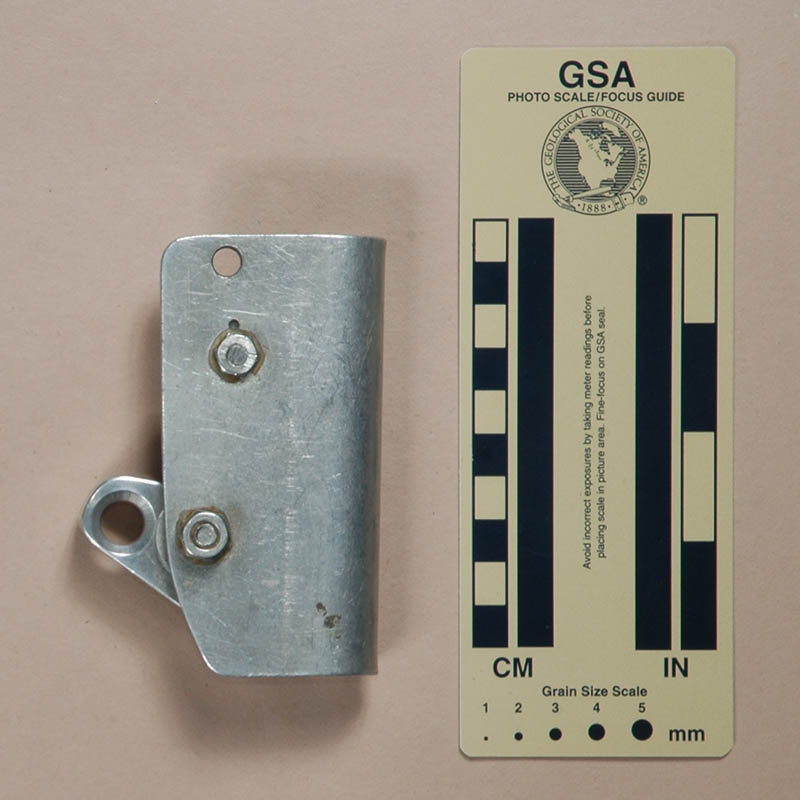
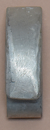
Homemade Version A
(#111)
Technical Details
I have no record of when or where I acquired this ascender, but it was before 1991.
Version A is 109 mm. tall, 65 mm. wide, 38 mm. thick, and weighs 161 g. The shell is bent from 1/8-in aluminum. The cam is handmade from 5/8-in
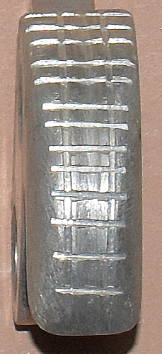
aluminum plate. The cam teeth are particularly crude, consisting
of a number of hacksaw cuts spaced about one blade-width apart.
Many of the "teeth" are broken. When I received this
ascender it had no pivot. It is shown with a 5/16 inch bolt, although
the holes are drilled to accept a 3/8 inch bolt.
I have no information on the history of this ascender. This
ascender was clearly patterned after an early Gibbs Ascender.
The shell looks like it was professionally
made, but the dimensions are not the same as a Gibbs shell, so I assume it isn't one.
[ Top
| v. A
| v. C
| v. D
| v. E
| v. F
| v. G
| LWO
| "S" v. A
| "S" v. B
| Return to L.C. Ascenders
]
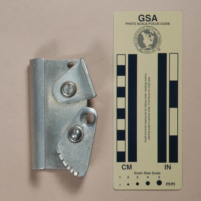
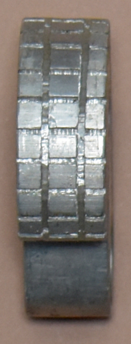
Homemade Version B
(#137)
Technical Details
I bought this ascender at the NSS Convention auction in 1999. Bob Thrun got the other one of the pair, but I acquired it in 2017 as part of Bob Thrun’s collection.
Version B is 103 mm. tall, 58 mm. wide, 39 mm. thick, and weighs 409 g. The shell on this ascender is made from 2.9 mm
steel sheet bent to form a U-shaped channel. The cam is cut from
1/2-in (13 mm.) steel plate. The eye was drilled, countersunk,
and then rounded. The cam face has 5 V-shaped grooves, forming
5 distinct teeth. The cam pivots on a 3/8-in bolt which is secured
by a hex nut. The bolt and nut were drilled to accept a cotter
pin.
I don't know this ascender’s history,
but one glance at the cam and one cannot help thinking of figure
1 in Henshaw & Morehouse’s article in the November 1965
NSS News.
This ascender is quite functional, but being made of steel,
it is also heavy.
[ Top
| v. A
| v. B
| v. D
| v. E
| v. F
| v. G
| LWO
| "S" v. A
| "S" v. B
| Return to L.C. Ascenders
]
Homemade Version C
(#3440)
Technical Details
 I acquired a pair of Unknown Homemade, Version C ascenders from eBay seller cptnamerica2003 in 2021.
Version C is 102 mm. tall, 63 mm. wide, 78 mm. thick, and weighs 209 g. The shell on this ascender is made from 2.9 mm
aluminum alloy sheet bent to form a U-shaped channel. The rope channel is 19 mm. wide.
The cam is cut from
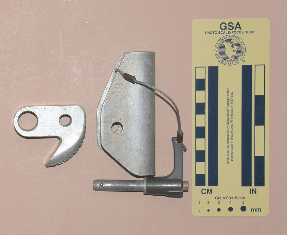
19 mm. aluminum alloy plate. The eye was drilled and chamfered. The cam radius increases from 18 to 43 mm. over an angle of 138°, giving a 20° cam angle. The cam face has 13 (or 16 on the other) horizontal and two vertical hand-cut saw grooves and a filed rounded central groove forming rudimentary teeth. The cam pivots on a 9.2 mm. L-handle QR pin.
The PR pin handle has "SPARE LOK INC" and "<PRESS" in raised letters on the outside of the handle, and is stamped with "NAS 1336-13" on the lower side.
I don't know this ascender’s history, other than it was in a set of equipment that included two Roloff racks, among other things. Because of their similarities and having obtained them all from the same source, I believe that Versions C, D, E, and F were made by the same person at roughly the same time.
The QR pin is a tight fit. I would have used slightly larger holes in the shell and cam to provide more clearance for mud and sand.
[ Top
| v. A
| v. B
| v. C
| v. E
| v. F
| v. G
| LWO
| "S" v. A
| "S" v. B
| Return to L.C. Ascenders
]
Homemade Version D
(#3511)
Technical Details
 I acquired an Unknown Homemade, Version D ascender from eBay seller cptnamerica2003 in 2022.
Version D is 102 mm. tall, 70 mm. wide, 78 mm. thick, and weighs 202 g. The shell on this ascender is made from 2.9 mm
aluminum alloy sheet bent to form a U-shaped channel. The rope channel is 20 mm. wide.
The cam is cut from
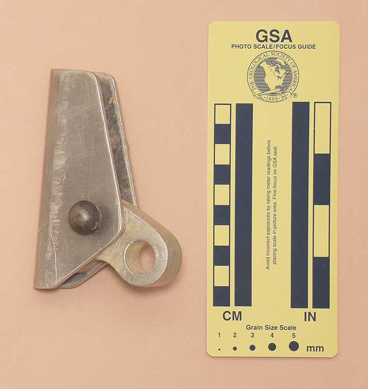
19 mm. aluminum alloy plate. The eye was drilled and chamfered. The cam radius increases from 17 to 41 mm. over an angle of 164°, giving a 17° cam angle. The cam face is smooth with no teeth. The cam pivots on a 9.2 mm. L-handle QR pin.
The PR pin handle has "SPARE LOK INC" and "<PRESS" in raised letters on the outside of the handle, and is stamped with "NAS 1336-13" on the lower side.
I don't know this ascender’s history. Because of their similarities and having obtained them all from the same source, I believe that Versions C, D, E, and F were made by the same person at roughly the same time.
The QR pin is a tight fit, but that is not the worst part. The cam will not pivot freely because the holes on each side of the cam are not aligned. I have no way of knowing whether these were drilled independently or the maker made the cardinal sin of drilling the holes before bending the shell, but in either case, the error ruined this ascender. This may explain why the builder never added teeth to the cam, and why it shows no sign of ever having been used.
[ Top
| v. A
| v. B
| v. C
| v. D
| v. F
| v. G
| LWO
| "S" v. A
| "S" v. B
| Return to L.C. Ascenders
]
Homemade Version E
(#3512)
Technical Details
 I acquired an Unknown Homemade, Version E ascender from eBay seller cptnamerica2003 in 2022.
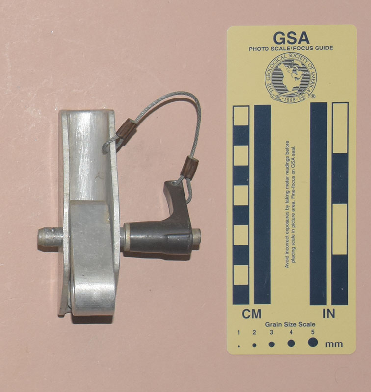
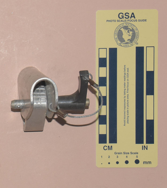
Version E is 100 mm. tall, 61 mm. wide, 78 mm. thick, and weighs 192 g. The shell on this ascender is made from 2.9 mm
aluminum alloy sheet bent to form a U-shaped channel. The rope channel is 19 mm. wide. There is an 11 mm. hole drilled in the rope groove near the top of the shell.
The cam is cut from
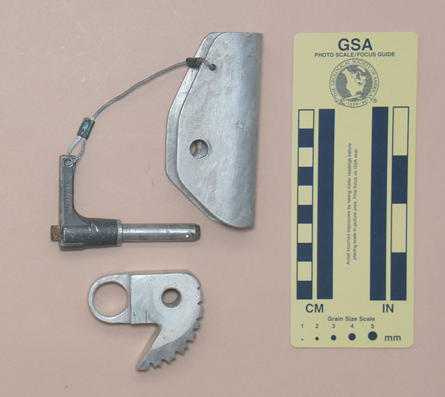
19 mm. aluminum alloy plate. The cam has been notched on each side of the eye, reducing the thickness at the eye to 9.3 mm. The eye was drilled and chamfered. The cam radius increases from 18 to 41 mm. over an angle of 135°, giving a 20° cam angle. The cam face has eight deep horizontal grooves alternating with seven shallow ones, and two vertical hand-cut saw grooves and a filed rounded central groove forming rudimentary teeth. The cam pivots on a 9.2 mm. L-handle QR pin. A 1.6 mm steel cable keeper connects the pin to the shell.
The PR pin handle has "SPARE LOK INC" and "<PRESS" in raised letters on the outside of the handle, and is stamped with "NAS 1336-13" on the lower side.
I don't know this ascender’s history. Because of their similarities and having obtained them all from the same source, I believe that Versions C, D, E, and F were made by the same person at roughly the same time.
The QR pin is a tight fit. I would have used slightly larger holes in the shell and cam to provide more clearance for mud and sand.
[ Top
| v. A
| v. B
| v. C
| v. D
| v. E
| v. G
| LWO
| "S" v. A
| "S" v. B
| Return to L.C. Ascenders
]
Homemade Version F
(#3513)
Technical Details
 I acquired an Unknown Homemade, Version F ascender from eBay seller cptnamerica2003 in 2022.
Version F is 108 mm. tall, 56 mm. wide, 78 mm. thick, and weighs 213 g. The shell on this ascender is made from 1.3 mm
steel sheet bent to form a U-shaped channel. The top and bottom are flared outward where the rope enters and exits. The rope channel is 16 mm. wide. There are two 13 mm. holes drilled through the shell above the cam.
The cam is cut from
16 mm. aluminum alloy plate. The eye was drilled and chamfered. The cam radius increases from 17 to 27 mm. over an angle of 136°, giving a 10° cam angle. The cam face has ten horizontal and two vertical hand-cut saw grooves forming rudimentary teeth. The cam pivots on a 9.2 mm. L-handle QR pin.
The PR pin handle has "SPARE LOK INC" and "<PRESS" in raised letters on the outside of the handle, and is stamped with "NAS 1336-13" on the lower side.
I don't know this ascender’s history. Because of their similarities and having obtained them all from the same source, I believe that Versions C, D, E, and F were made by the same person at roughly the same time.
The QR pin is a tight fit. I would have used slightly larger holes in the shell and cam to provide more clearance for mud and sand.
[ Top
| v. A
| v. B
| v. C
| v. D
| v. E
| v. F
| LWO
| "S" v. A
| "S" v. B
| Return to L.C. Ascenders
]
Homemade Version G
(#3615)
Technical Details
 I acquired a pair of these ascenders from on eBay from Barry J. Rousey in 2023.
The Unknown Homemade, Version G is 108 mm. tall, 63 mm. wide, 52 mm. thick, and weighs 168 g. The rope channel is 16 mm. wide. The cam radius increases from 18 to 30 mm. over an angle of 111°, giving a 14° cam angle. The tooth pattern is .
Version G is 108 mm. tall, 63 mm. wide, 52 mm. thick, and weighs 168 g. The shell on this ascender is made from 3.2 mm
aluminum sheet bent to form a U-shaped channel. The rope channel is 16 mm. wide. There are two 13 mm. holes drilled through the shell above the cam.
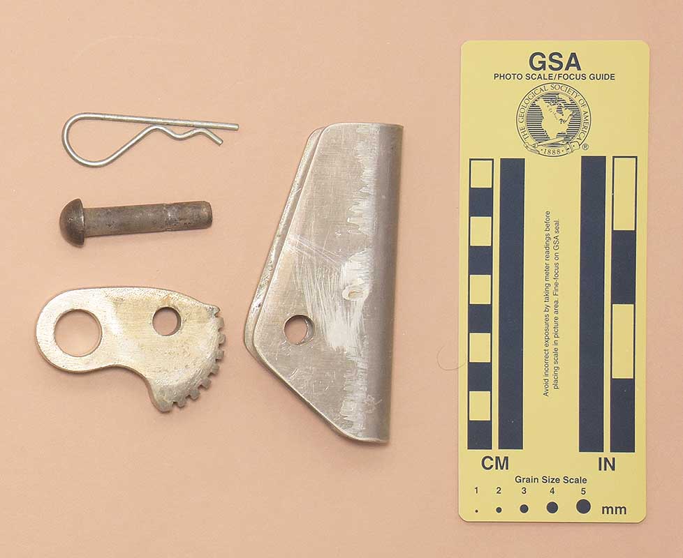
The cam is cast from aluminum alloy, but the teeth are cut. The eye was finished by drilling. The cam radius increases from 18 to 30 mm. over an angle of 111°, giving a 14° cam angle. The cam face has eight horizontal grooves forming square-ishs teeth. The cam pivots on a 3/8" rivet that was cross-drilled to accept a hair pin.
Barry found this rack and several other vertical caving devices in the bottom of a box of rope that he bought at a garage sale in Knoxville TN. It is obvious from the selection that the original owner was a caver, but I have not identified who (s)he was.
The marks on the shell show that it was formed by pressing the aluminum plate into a groove. Bob Thrun recommended this technique in his book Prusiking (fig. 39). If the maker was following Bob's book, then these ascenders probably date from the early 1970s.
The rivet could be about 10 mm. shorter and still function just as well.
Lacking any keepers, there is an increased chance of losing parts while rigging or derigging these ascenders.
[ Top
| v. A
| v. B
| v. C
| v. D
| v. E
| v. F
| v. G
| "S" v. A
| "S" v. B
| Return to L.C. Ascenders
]
LWO Homemade
(#90)
Technical Details
I have no record of when and where I acquired this ascender, but it was before 1991.
The LWO is 101 mm. tall, 68 mm. wide, 47 mm. thick, and weighs 270 g. The
shell is bent from 1/8 inch aluminum plate. It appears that either
a scrap piece of aluminum was used, or the lowest grade sheet
metal was sought, because the finish is horrid. The cam is built
from two pieces of 3/8-in aluminum plate made into a 3/4-in thick
cam by clamping the two pieces together, drilling and tapping
them, bolting them together, and then cutting the bolt heads off.
The cam teeth are formed by a series of hacksaw cuts, done with
more care than on the preceding or following ascenders. The axle
is a steel pin with a hole at the end. It is secured by a spring
wire retainer that appears to have come from a Gibbs
ascender.
I have no information on the history of this ascender,
but the initials "LWO" engraved in the shell suggest that it might have come from my friend Lynn W. Ott.
[ Top
| v. A
| v. B
| v. C
| v. D
| v. E
| v. F
| v. G
| LWO
| "S" v. B
| Return to L.C. Ascenders
]
Unknown "S," Version A
(#250)
Technical Details
I acquired two Unknown "S," Version A ascenders from
Bill Boehle at the 2008 Old Timers Reunion.
The Unknown "S," Version A is 102 mm. tall, 69 mm
wide, and 29 mm. thick. Mine weighs 139 g.
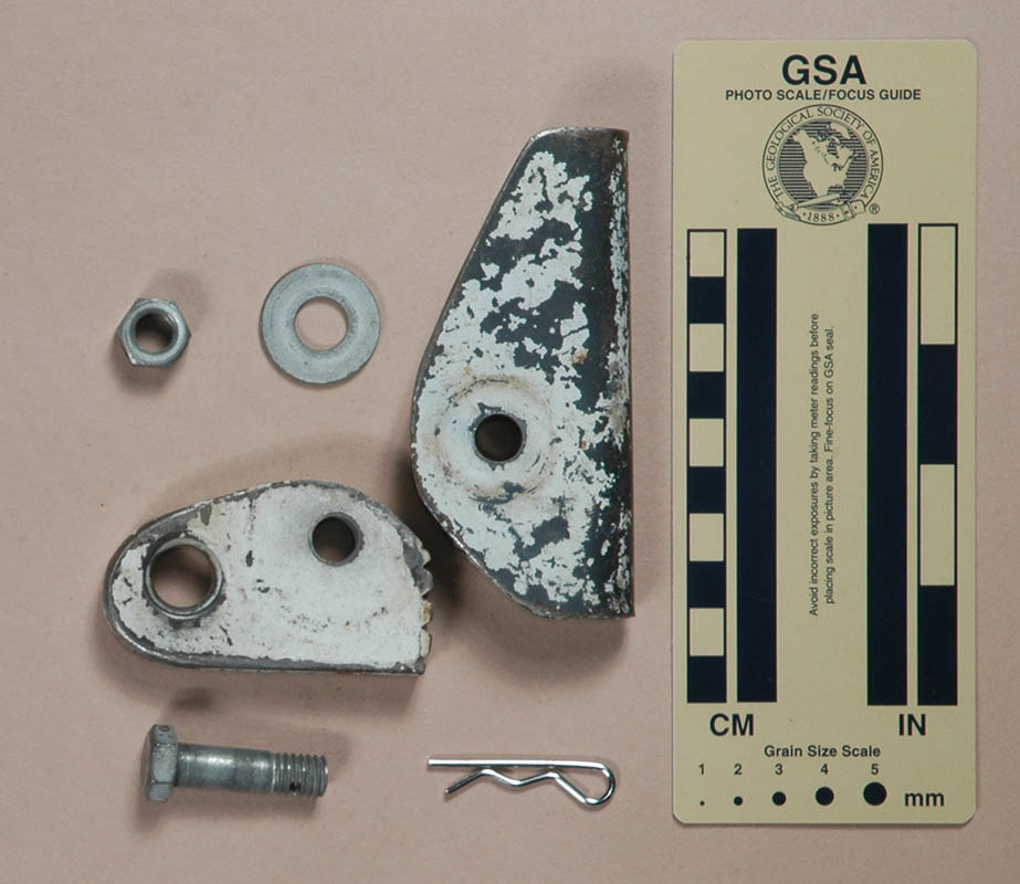
The shell is made from 3.2 mm. aluminum sheet bent to
form a 15.7 mm. semicircular rope channel on one side. There
is a 6.4 mm. hole drilled near the top of the shell for attaching
a bungee. The cam is cut from 12.5 mm. aluminum plate. The
cam radius, measured from the axle (and ignoring the rounded toe
and heel), increases from 25 to 38 mm. over an angle of 40°,
giving a 30° cam angle. The attachment point is a 10.3 mm.
chamfered hole centered 18 mm. from the axle. The axle is
a 1/4-20UNC slotted round head machine screw. There is a steel
washer on the outside of the cam, a plastic washer between cam
and shell, and a hex nut behind the shell.
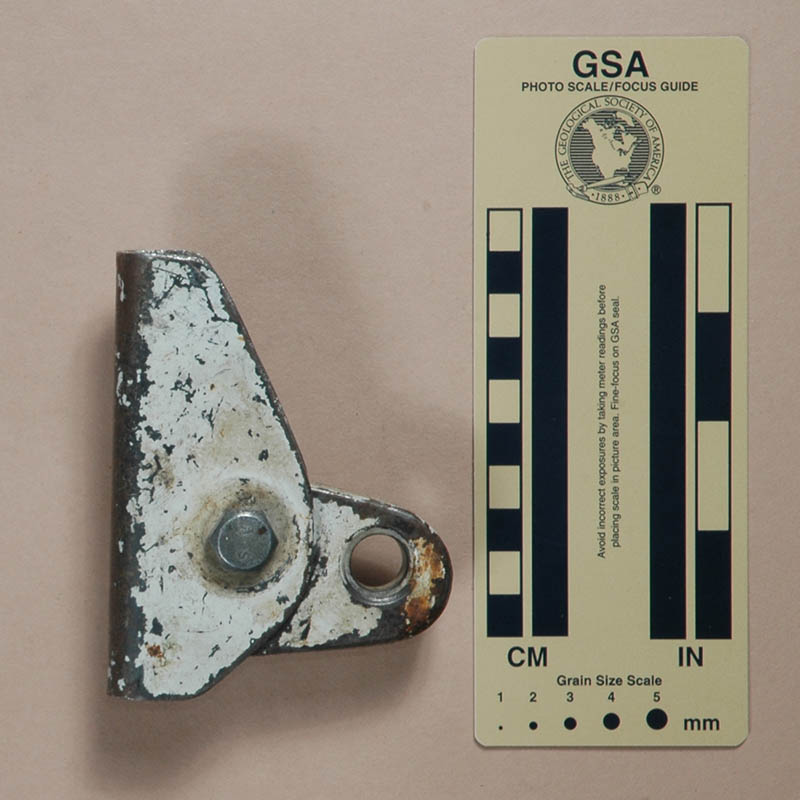
The cam safety is cut from 3.1 mm. aluminum angle. It
pivots on a countersunk #12 machine screw held in place with a
hex nut. When closed, the safety interferes with opening the cam.
What a clever little design! This ascender has an open side
like the Paquette, but the cam
safety is much easier to operate. Using aluminum for the shell
makes this ascender much lighter than the Paquette,
but the Paquette is undoubtedly
stronger. Assuming a reasonable weight caver using this as an
ascender (like it was designed to be), the strength is sufficient.
Bill did not know who made these ascenders, but there was an
"S" painted on some of the other equipment in the gear
set that these came from.
[ Top
| v. A
| v. B
| v. C
| v. D
| v. E
| v. F
| v. G
| LWO
| "S" v. A
| Return to L.C. Ascenders
]
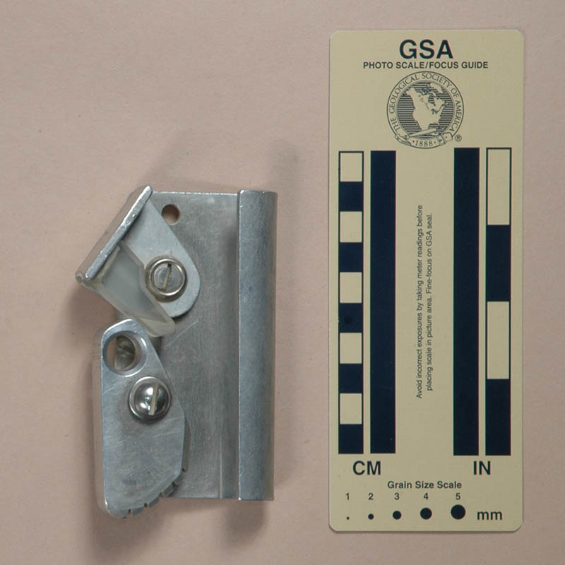
Unknown "S," Version B
(#251)
Technical Details
I acquired my Unknown "S," Version B from Bill Boehle
at the 2008 Old Timers Reunion. The Unknown "S," Version B is 101 mm. tall, 70 mm. wide, and 30 mm. thick. Mine weighs 143
g.
Version B is a left-hand ascender. Aside from being a
mirror image of Version A, it adds a plastic guide epoxied
to the top of the cam safety.
The plastic guide helps keep the ascender from tipping when
pulled upward by the cam eye, as it might be, for example, when
tied to the foot as a foot ascender. This is a nice idea, but
I would have drilled and tapped the plastic and used a machine
screw to hold it in place rather than relying only on epoxy. Bill
believes that one of the Version A ascenders used to have
a guide glued to it, but I'm not so sure, I don't see clear evidence
of this.
[ Top
| v. A
| v. B
| v. C
| v. D
| v. E
| v. F
| v. G
| LWO
| "S" v. A
| "S" v. B
]